

Thanks!Originally Posted by Mark_Spit

I'm still working on it.. also thinking about changing the knobs. The EQ pots are actually knurled shaft, and the rest are screw-type so to get an uniform look I'd have to switch the potentiometers..


Thanks!
I'm still working on it.. also thinking about changing the knobs. The EQ pots are actually knurled shaft, and the rest are screw-type so to get an uniform look I'd have to switch the potentiometers..
Made a smaller version just for fun from what was left from the original build.. it's missing knobs though.
Tested the latter with a 1MOhm resistor in the output ground..
Here's an old mixer sketch ca. 2006
The current build has resistors now in the output but the HP amp is dead.. (the small one was taken apart because I needed parts for the crossover)
In my spare time I started designing a relay-operated priority control feature which mutes the output from the summing amp by connecting two wires (+/- from PSU to the relays) and leaves a mic channel open (Swissonic ZM4 has a similar feature) but for long mic cables it'd need an active DI box (or a phantom feed)
A quick workaround would be a separate box with master&zone I/O (there really is no space in my current build)
EDIT : energized relays could cause noise however.. unless they're solid state.
EDIT 2 : something like this :
EDIT 3 : to prevent "misuse" there are a few options; either to relay the priority channel as well or to pair an on/off switch (powering the relay turns on the mic) with the priority input and seal it (something they use in power distribution I read, ie. if a change was made it'd be thoroughly investigated, this is to prevent anyone from deliberately ruining someone's set remotely and blaming it on them or rest of the signal chain etc) Then it only needs to be tested once in a month or so. Highly useful feature in an installation mixer in case of an emergency, fire, shooting etc where the path between the mixer/DJ booth and the bar could be blocked by audience I think. A fire alarm/sprinkler system could be used to trigger it too but it'd need a buzzer or a tape loop/playback module (ISD1820?) with a prerecorded message.
The venue I used to play at had a door from the booth to the bar in addition to the route across the main room (from the bar to the booth the door was locked) but during busy nights there could've been 20-50 people standing in the way, so the bartender/doorman couldn't make it to booth without either stagediving or breaking the door (which is why I designed the circuit in the first place, it's like a few relays, a couple of connectors and 2x30m 2/3 conductor cable max because of voltage drop and depending on whether there's phantom feed I'd think, and a SMPS in the control panel to power the relays.. it needs a mic too, with a DI/preamp in the same remote end if there's no +48V)
Last edited by efinque; 03-05-2020 at 05:47 AM.

cool, advanced techy stuff
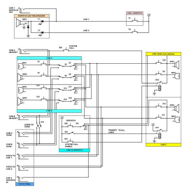
Here's the "balanced" version of the priority relay with an emergency tone function.
Relays 4,5 and 6 are to prevent the mono sum during normal operation.
Last edited by efinque; 03-20-2020 at 02:57 PM.
Anyway, the current build is unfortunately mono due to the headphone amp summing the signals.. I was thinking of establishing the sum point post the headphone amp and wiring all the grounds to a star point from the summing bus.. this is just me being lazy but the EQ sums the grounds anyway, and running separate ground signals isn't even possible with standard TRS jacks. The troublesome part is the 2x6-pos rotary switch which is a nightmare to wire&solder, a 3-pole L/R+gnd would effectively solve it but I was thinking of doing a cue/pgm PFL section in my spare time; basically feed the HP amp inputs via a voltage divider with the left TRS ch as cue and right with pgm (and a switch to run it with cue only)
Meanwhile I've been plotting a fader mixer with per channel HPF as well as an intercom.
Another thing I noticed is the crossover I built does the same mono summing in the LF which affects the stereo HF, I've also been trying to look into that.. afaik the only solution is to run the LF as stereo and sum it at the output with resistors or just use either L or R as the source, as diodes generally have a ~0,7V forward voltage.
In practice I think running audio stuff in mono is ok but internally both the mixer and the crossover (not pictured in this thread) are virtually "stereo-compatible"
Last edited by efinque; 03-24-2020 at 02:27 PM.

Use plastic body jacks if you want ground isolation.
The way you prevent summing between buses in a mixer is by mixing low impedance outputs to high impedance inputs. So, let's say you want to sum the output of two channels, but you also want to keep them separated so that you can cue them. You isolate them with a high value resistor in series, like so:
It works because the amp stages have a high input.impedance and a low output impedance, so a high value resistor from output to input doesn't attenuate the signal much. But signals that go the other way are attenuated. .
This is how literally every analog mixer works and why yours hasn't been working the way you want.
Last edited by light-o-matic; 03-24-2020 at 12:27 PM.
What's the reason behind this exactly? Touching the ground shouldn't do anything in theory, in some cases it even attenuates the hum.
The schematic you posted is technically correct but once you go stereo with a mono PFL you need summing (or output) resistors in the cue, otherwise you'd need to be cueing only left or right since the mono bus creates a shunt between the stereo channels (think of having hot and cold water pipes and mixing them prior to the tap)The way you prevent summing between buses in a mixer is by mixing low impedance outputs to high impedance inputs. So, let's say you want to sum the output of two channels, but you also want to keep them separated so that you can cue them. You isolate them with a high value resistor in series, like so:

I understand the basic theory of operation but resistors generate noise and the larger values you use the more amplification you need after the summing, ie. gain staging.. while in a headphone bus it doesn't matter (and you could probably even use electrolytic capacitors) you're still left with L/R+mono where the underlying total resistance of the mono signal across the two channels is formed via the resistors (in other words you get a quiet mono sum in the background)It works because the amp stages have a high input.impedance and a low output impedance, so a high value resistor from output to input doesn't attenuate the signal much. But signals that go the other way are attenuated. .
EDIT : to further elaborate the intercom project started off as a "joke" as I've built one about 15 years ago.. I refined the idea a bit further though so it's closer to a PBX/telephone exchange with an automatic call handler but I haven't gotten around to building it yet.
Consumer and pro audio which both have different technical needs aren't like "enterprise" solutions where very impressive things are done with as little as 1-5W, sometimes within a narrow frequency range (400-4kHz) over long distances, main concerns being effeciency, speech intelliglebity and ease of use whereas pro audio is mostly concerned about balanced transmission, wide frequency response and large power handling capability.
Last edited by efinque; 03-24-2020 at 03:15 PM.
 Posting Permissions
 The knobs at the top look a tad bit big tho...
 Reply With Quote


Bookmarks