Results 1 to 9 of 9

Thread: PMC-05 ProII Rescue/Upgrade

  1. #1
    Member djpenguin's Avatar
    Join Date
    Feb 2012
    Location
    Oakland, CA
    Posts
    345

    PMC-05 ProII Rescue/Upgrade

    Recently I was helping my brother move, and he gave me a broken PMC-05 ProII mixer. It didn't power on, and it was missing all the knobs and the top (gold-colored) faceplate.

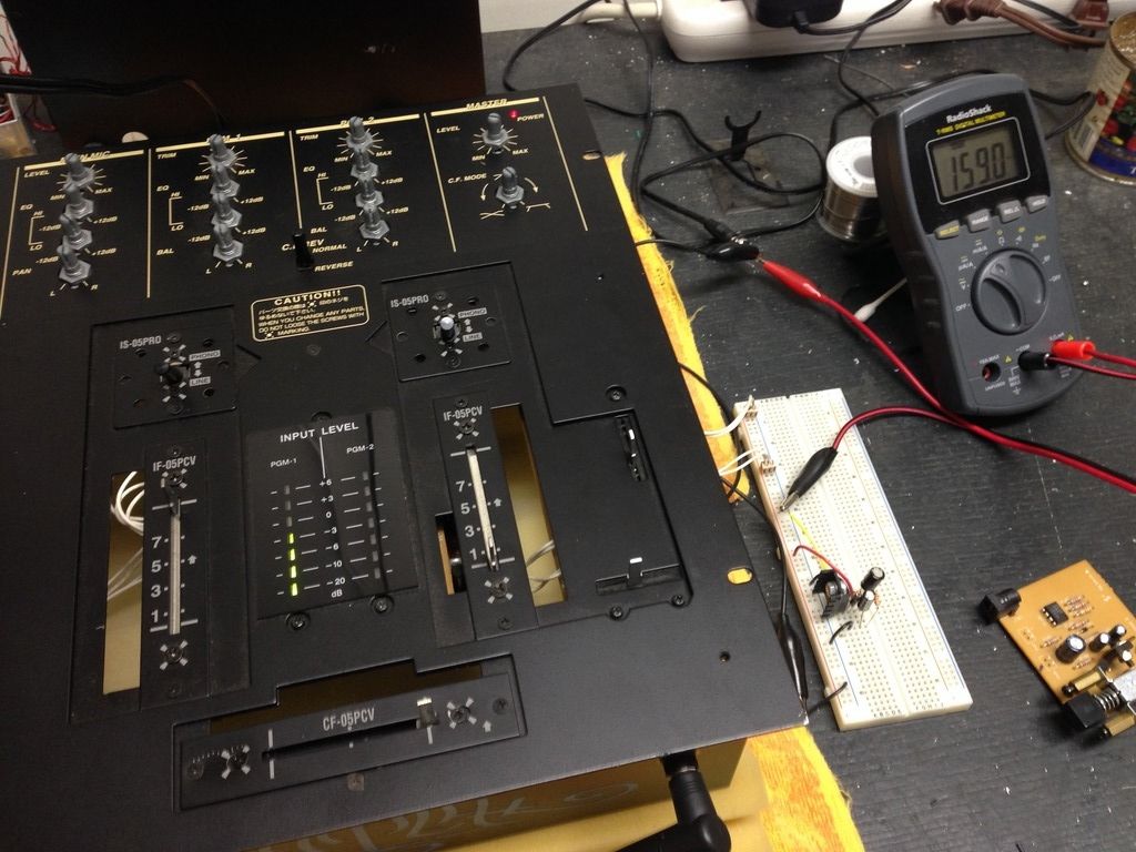
    The first order of business was figuring out why it wouldn't power on. A little testing with a voltmeter told me that the power regulator board wasn't supplying any significant voltage to the rest of the electronics, so I began working on a replacement. I decided to use a single adjustable voltage regulator instead of the opamp-based voltage reference design originally used, because I already had the necessary parts.


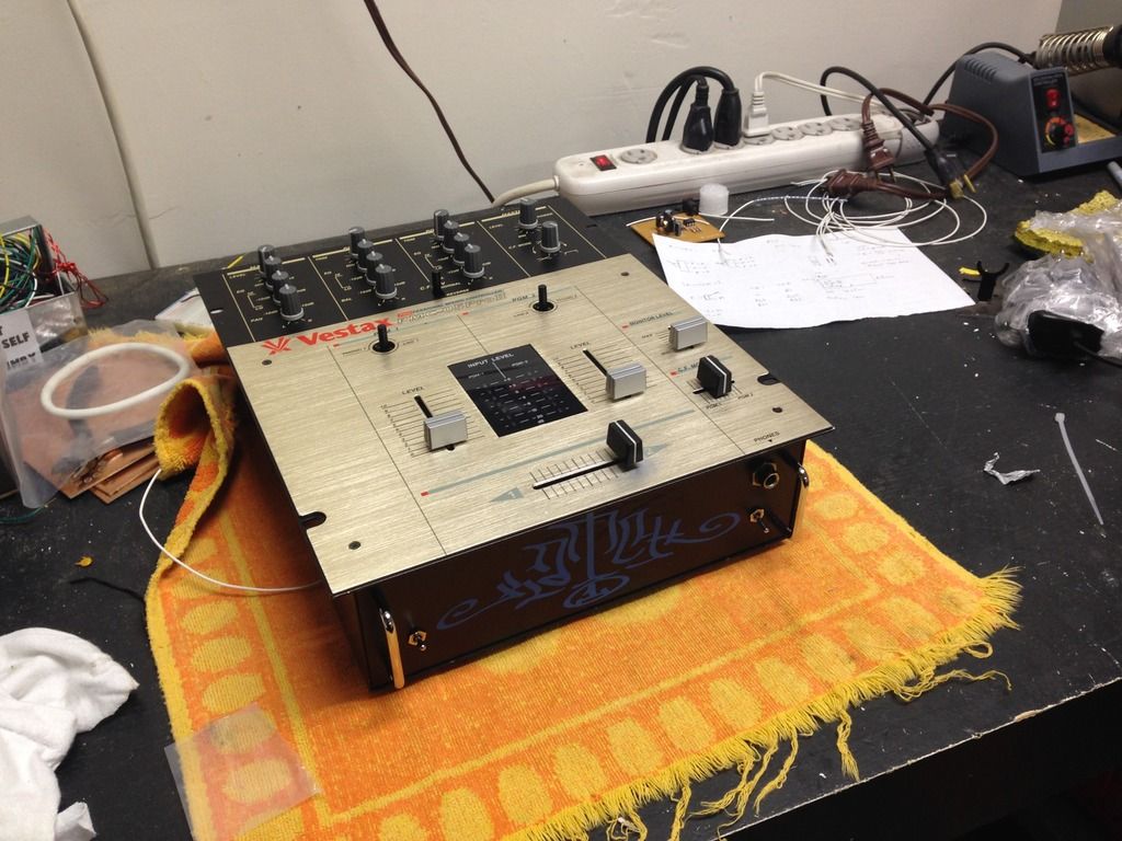
    The mixer being powered by the new design (on the breadboard), with the inoperative original board on the right

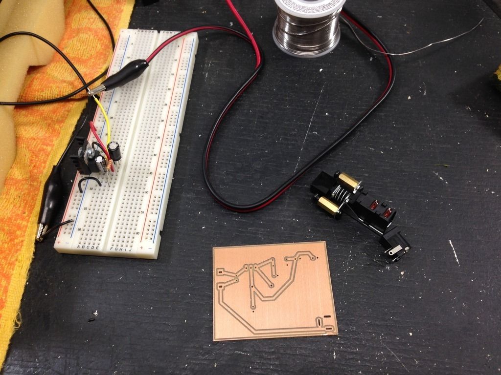
    Having verified that the mixer worked fine with the new regulator design, I designed a PCB to hold the new design. I wasn't able to obtain a replacement switch that matched the original, so I removed the original switch from the old board and re-used it.


    The PCB for the new design with the old switch and a new power jack


    It fits!

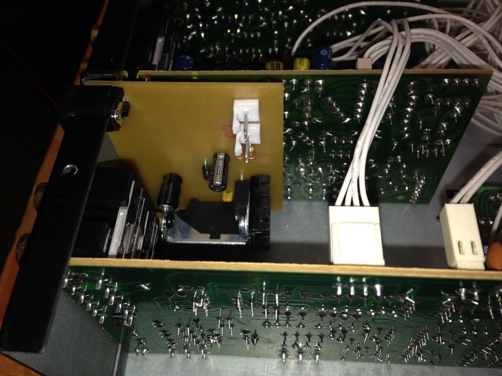
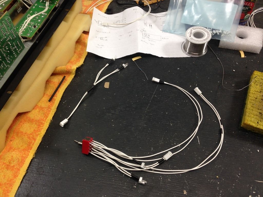
    While I was working on the power supply, I noticed that the mixer internals were configured in such a way that I could fairly easily modify the monitor section and meters to switch between their default (per-channel) inputs and inputs from the master section of the mixer. In order to make this mod, I needed to add some leads to the master section PCB, make a splitter cable, and wire a couple of 4PDT switches.


    Splitter cable and one of the switches

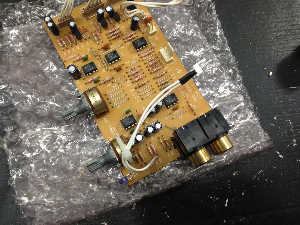
    While I had the master section PCB out of the mixer, I decided to replace the red LED with a blue one.


    Master PCB with new leads (zip-tied to a potentiometer for strain relief) and blue LED

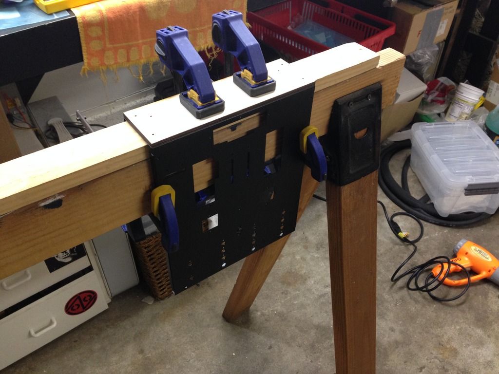
    I decided to mount the new switches on the front panel of the mixer; I also decided to add small handles to the front to protect the new switches. I made a template to make sure the holes would be evenly spaced, then removed all the components from the top part of the case.


    The top case ready for drilling


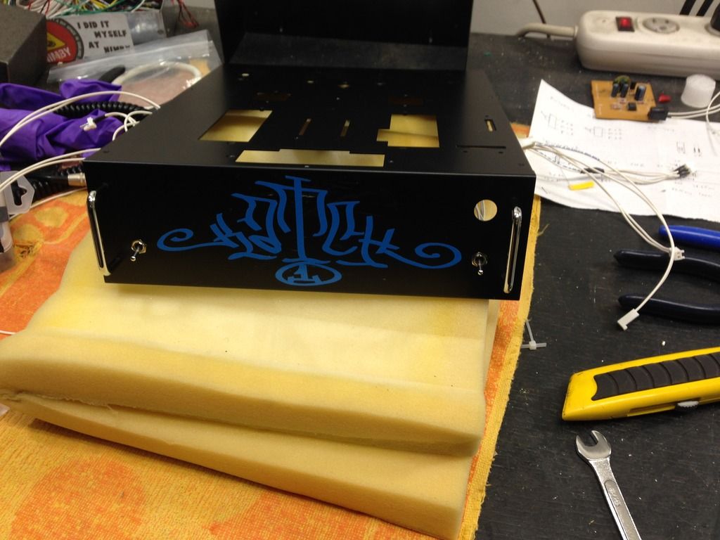
    Switches and handles mounted


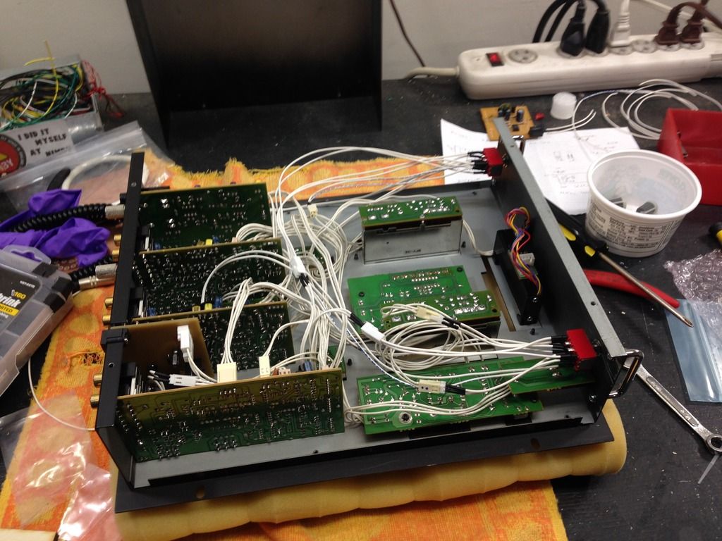
    Everything reassembled

    For the finishing touches, I bought a used replacement faceplate on eBay, and some rubberized knobs from an electronics store.


    All done!
    Click here for mixes!
    Quote Originally Posted by Mahatma Coat View Post
    I once DJ'd to a room of 500 Shoreditch hipsters using only my rigid cock and a empty jar of Marmite

  2. #2
    Great freakin work! It looks and functions better than it originally did.
    QSC GTDaudio B52 Numark NS7 American DJ Hercules 4Mx ACER Behringer Peavey Koss CerwinVega Selenium VDJ= Sweet Music
    Owner DRZ Inc.

  3. #3
    Moderator pete's Avatar
    Join Date
    Feb 2012
    Location
    old orléans
    Posts
    2,528
    Cool!

    At some point I need to take apart my Urei 1601 and repair the power supply section...
    bored, curious, deaf or just bad taste in music?
    finally a mix by me
    and what's this, another shoddy mix...another dull mix

  4. #4
    Nice job, djpenguin!
    www.dnbradio.com

    Quote Originally Posted by Doppelganger
    He's just like me, only he's a man and more stupid

  5. #5
    Batman andymunro's Avatar
    Join Date
    Feb 2014
    Location
    North West - England
    Posts
    1,111
    That's brilliant work, I've been putting off just buying replacement faders for my vestax pcv-275 in case i ruin it!
    * Follow me on Twitter * My latest mixes on Soundcloud / Hear This * All downloads on Hulkshare *
    andymunro.blogspot.co.uk for my tracklistings and links to my 320k mp3 downloads

  6. #6
    Moderator Mark_Spit's Avatar
    Join Date
    Feb 2012
    Location
    Stoopid Markham / Dumb Toronto
    Posts
    787
    Incredible work penguin!

    Just one question: Did you make that additional board - if so, how?
    Ya gotta love corn, it's one of the only foods that says good-bye.

    Rep owed: DTR, Pete, KLH, mitchiemasha,

  7. #7
    Member djpenguin's Avatar
    Join Date
    Feb 2012
    Location
    Oakland, CA
    Posts
    345
    Quote Originally Posted by Mark_Spit View Post
    Incredible work penguin!

    Just one question: Did you make that additional board - if so, how?
    Yes. I used CadSoft's EAGLE software to make the custom footprints for the switch and power jack and lay out the PCB. I made the PCB on an Othermill desktop CNC mill at school.
    Click here for mixes!
    Quote Originally Posted by Mahatma Coat View Post
    I once DJ'd to a room of 500 Shoreditch hipsters using only my rigid cock and a empty jar of Marmite

  8. #8
    Moderator Mark_Spit's Avatar
    Join Date
    Feb 2012
    Location
    Stoopid Markham / Dumb Toronto
    Posts
    787
    Nice!

    I remember seeing Othermills a while back and thought they'd be ideal for the scale of work I normally do. However I have no experience with the software.
    Ya gotta love corn, it's one of the only foods that says good-bye.

    Rep owed: DTR, Pete, KLH, mitchiemasha,

  9. #9
    Member djpenguin's Avatar
    Join Date
    Feb 2012
    Location
    Oakland, CA
    Posts
    345
    EAGLE is pretty easy to use, and there are a lot of tutorials out there. You just have to jump in.

    The best part about using EAGLE with the Othermill is that the milling software (Otherplan) reads the EAGLE board files directly, with no need to export to Gerber.
    Click here for mixes!
    Quote Originally Posted by Mahatma Coat View Post
    I once DJ'd to a room of 500 Shoreditch hipsters using only my rigid cock and a empty jar of Marmite

Posting Permissions

  • You may not post new threads
  • You may not post replies
  • You may not post attachments
  • You may not edit your posts
  •  
a